For the soon to be engineers : Choosing the right stream of engineering !

A lot of young minds who have just answered 12th and other entrance exams are often recommended by several adults / peers HiRes-1024x921to pursue the field of engineering. Reasons for such encouragement of said pursuit often vary. A few being: wide career options and career growth, social status, following well trodden path to achieve success and life goals.

But often we forget what the young minds themselves want to pursue. I myself was one such case, ready and eager to jump into the field of engineering but confused as to which stream to chose. So I’m writing this article in the most simple and easy to understand manner for those students who are in the same boat as I once was, at the tender junction between Higher Secondary and College, as the choices made here affect every aspect of life henceforth. But remember this isn’t a career counseling guideline but just a humble effort to give students who want to become engineers an idea of the some of the basic fields they can choose from and what is in-store these courses.

I’ll start with the field I chose and enjoyed and grew into eventually which is Electronics and Tele-communication. Firstly the Arduino-LED-light-bar-1reasons behind my choice were, my cupboard was always filled with toy robots and I always wanted to make them and all toppers were choosing this field at the time simply because we were told that placements i.e. students who had an assured job during final year campus interviews was the highest in this course at the time. The placements situation keeps changing even during the four years of engineering after making the choice of field. So do not let placements be a large deciding factor.

So, Electronics and Tele-communications is all about learning how electronics work at the very base level and all the theories of working of the components that form the foundation of all electronic circuits made till date. Some of which include resistors, capacitors, diodes, transistors. Once the ground level devices are done analyzing in various depths, we then learn how combinations of such devices have made all the technologies developed till date possible. Of course you will be learning about many integrated circuits, how to build them, Communication devices and their components and a lot of other aspects of electronics such at Networks , Power Electronics, Understanding and analyzing signals both digital and analog and also coding / programming for but not limited to various microcontrollers and microprocessors. You will also learn programming in different computer languages as even after completing this course you are likely to get placed in an IT firm. This is as brief as I could get with the four years of data that is passed on to every engineer in this field.

The next field is closely related field to Electronics and Tele-communications which is Electronics and Electrical. Most of the topics covered are same as or closely related to E&TC with the major difference being is more emphasis on devices that are the building blocks to all are power and energy requirements and less emphasis on communication aspects. To name a few transformers, motors, power lines their etc. Analyzing and understanding equipments which work at very high voltages is also a major part of this course. But again computer programming basics is also covered in this course as well.

With my experience the above courses are good for students who want to learn about consumer electronics, appliances, robotics and automations systems.

Ok so thus far I’ve covered two specializations which I know a thing or two about. So to be sure I’m giving accurate and up to date information in this article I asked a few of my colleagues who too pursued engineering with a similar mindset as me but chose different areas for specialization.

Let’s look at what Mr. Darshan Sardesai(B.E. IT) who has recently completed his PGDM in MBA from GIM has to say about the csmost booming industry and has the highest yearly intake of engineers all over India which is Information Technology in short IT. In this field as the name suggest you will study several programming languages some of which are C, C++, JAVA, etc. Each of them will be covered thoroughly and there is very little emphasis on hardware or mechanical aspects of engineering study. Some other aspects of IT covered will be software testing, IT security , Database management, Study of Graphical user interfaces which include web page designs and associated languages and you will also learn about new age IT services like cloud computing and even some Business aspects of IT . Darshan says “If you are inclined towards coding and developing algorithms for complex problems this is the field for you

Now for the most preferred field amongst those who grew up with a passion for bikes, cars, planes and any real life object that can be put in motion using gears and grease: Mechanical Engineering and who better to give anmechanical-engineer-720 Idea about the same then a current faculty at Goa college of Engineering in the same line Mr. Achintya Kambli. This field teaches you the advanced principles of physics, materials science for design and analysis and also manufacturing and maintenance of such systems. You will also learn a lot about manufacturing processes as well as thermal and fluid sciences. And as it is with other fields bits and pieces of electronic, electrical and software studies are also a part of syllabus as well as management and planning. Making Mechanical engineers ready for any jobs available in the market. A lot of design is done on paper drawings but you will also learn to do the same using modern computer design software namely CAD. Achintya finally concludes by saying “This discipline changes your outlook towards life. If you are already a highly logical individual you will grow in this field. If you love working on the physical world, like to learn and make impact on/ help construct the building blocks of engineering, designing and manufacturing various mechanical machines you cannot go wrong with this field”

Now coming to the technology that revolutionized every aspect of our lives today after it came into existence that is, Computer Engineering. To shed some light on this area Ms. Akshay Shekher gave a few inputs on what you can expect from this field , if you are wondering who is Akshay and why him, well, he is one of the developers of a Linux based Operating System named Elementary OS. Akshay says Computer Engineering is closely related to but not the same as IT. The major difference being you will learn a lot of computer hardware along with software studies. To put it in simple words you will learn how programming languages work right at the ground level which is basically coding in Assembly (binary) or machine language. Thal akeep-calm-i-am-an-engineeris forms the basis of this course along with basic electronics subjects related to building digital machines as well. As the course progresses, you will learn about more complex algorithms that govern computers, data structures, computer networking and associated hardware. As stated previously a lot of programming languages are also a part of this course. Akshay advises that “This course will help you grasp concepts of both world that is electronics and IT and should be the choice of students who were always eager to learn about the workings of digital machines”.

Of course there are many more engineering courses like Civil, Chemical, Mechatronics(Combination of mechanical and electronics), Petroleum, Bio-Medical etc. But what you will learn in these is clearly evident directly in their names.

So a final note to all budding and enthusiastic engineers is choose the field you have an innate inclination towards , for that passion and drive is what will help you succeed in whatever field you may chose no matter which college or the hype behind placements etc in said courses. What all engineers eventually learn is that no matter which course you take, Engineering is not just a Degree, for most it then becomes a way of life.

Inventrom is organising a 5 day program for these budding engineers on Robotics which will give them hands on experience on Electronics, Mechanical and Software Development. This is an ideal way for students who are pursuing engineering to know the best way forward specially in choosing the right branch. To know more visit http://www.inventrom.com/12.php or feel free to call Ryan D’Costa on +91 9765117708

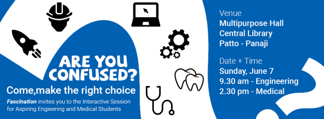
Another way to know more about choosing your stream is the interactive session by Fascination happening in Panjim, Central Library.  Call up Raj Kunkolikar on 09673374334 to know more about the event.

2015

This article is written by Mr.Dattaprasad Naik. Datta works on electronics and embedded design at Inventrom and has conducted workshops in Robotics, IoT and Raspberry Pi for corporates from IBM, Intel, SAP etc. as well as at various prestigious institutes like IIT Kanpur, VIT, IIST etc.

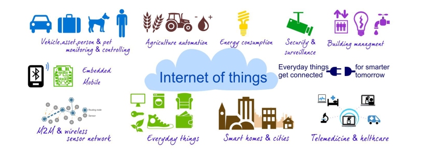
The “CLOUD” and “Internet of Things”

The “Internet of Things” is entering our lives and daily proceedings of businesses worldwide, slowly but surely.

This means connected cars, wearables, TVs, smartphones, fitness equipment, robots, ATMs, vending machines, and all of the associated applications, security and services, analytics and platforms that come with them.

Intel estimates, the IoT is predicted to have 4 billion people using 31 billion devices by 2020. IoT is looking to avail these applications and services worldwide on a massive scale, such a system will have to collect vast amount of data about user, consumer preferences and the “Things” itself and this is where the “CLOUD” comes into the picture.

No single organization has the capability to

  • Have a large enough database to store such high volumes of data that will be generated.
  • Processing power to work on the generated data

The Cloud will benefit IoT in the following ways

  • Data Analysis
    • Mining useful information of the data but using the decentralized processing power of the cloud
    • Better prediction capabilities which will help in advertising, targeted marketing, resource management and cost cutting.
    • Also help provide better services to consumers depending on their preferences
  • Support to Startups to pursue IoT
    • IoT still having a lot of scope for evolving innovation , and startups offering different IoT related devices and service , the cloud will provide easier and cheaper solution to these startups.
    • Allows smaller businesses to use sophisticated software for project and customer relationship management.
  • Report Generation
    • Users will be able to gain access to extensive reports on everyday objects that could not previously be tracked.
  • Automation
    • From transport systems to healthcare processes, this is quickly becoming a reality as embedded chips are sending vital information to the cloud, speeding up processes, and altogether solving universal management issues.
  • Security
    • With the rise of IoT, trust issues will remain at the top of the list as major concerns for the industry. In order to meet full potential in this new area of technology, privacy and security measures will have to be taken very seriously and carried out at the same speed, or even faster than the introduction of new objects.

Thus in conclusion:

Systems in the cloud will be used to (a) mine data into valuable information and (b) create productive, cost-effective actions from the mined information. Thus the cloud effectively acts as the brain to improve decision-making and optimization for Internet-connected interactions.

HiRes-1024x921

Img Source: http://emptechgroup.com/the-internet-of-things/

Thanks for reading 🙂

This post was written for Inventrom by Dattaprasad Naik. Datta has been working with Inventrom since 2013 and leads Learn, the department involved in training and workshops. Follow Datta on twitter via @datta_TECH

The “Thing” in “Internet of Things ”

What is this “Thing” i keep hearing about about so much?

Well in the English language nouns consists of Name, Place, Animal or Thing. Hence anything which is not a Name, Place or Animal, is definitely a Thing (ENGLISH 101). But the fact remains you aren’t reading this blog post to learn English (I’m assuming, if you are stop here 😉 ) and you are here to understand what is this “Thing”?, why is it important?, and how do we make it?, in context to the phrase “Internet of Things”.

So lets tackle each question one at a time so that by the end of this you can get a head start in understanding the phrase and idea behind the Internet of Things.

There are four main system components for the Internet of Things(IoT)

1>The Thing

2>The local network.

3>The Internet

4>The cloud

IoT is not complicated in conception, but it is complex in its execution.What is important to understand is that even if new hardware and software are still under development, we already have all the tools we need now to start making IoT a reality. In this blog post we’ll only cover the “Thing” the rest will be covered in future blogs so keep an eye on this page.

So this brings us to our first question

What is the “Thing”?

things

Img Source: datasciencebe.com

Thing is an embedded computing device (or embedded system) that transmits and receives information over a network (need not be able to interface with internet directly) for the purpose of controlling another device or interacting with a user. A Thing is also a microcontroller—or microprocessor-based device.

Hence a simple chair, tv , fan , microwave , fridge, sprinkler, bulb etc, (the list goes on) on their own cannot be called “Things”. Why you ask ?

1) Most of day to day things do not have any embedded systems E.g.: bed , chair, fan, bulb.

2) Even if they do have embedded systems built in, they do not have the capabilities too transmit and receive information over a network. E.g. washing machine, microwave, electric stoves.

Okay… So now you may ask what is this “Thing” supposed to do?

The “Thing” may provide

1>Identification and info storage(RFID tags, MAC address)

2>Information collection (Sensor networks, store sensor values)

3>Information processing(Understanding commands, filtering data)

4>Communications (Transmit and receive messages)

5>Actuation (Switch control, motor control)

Hence for anything to become a “Thing” in IoT we need to add the one or all of the above features to day to day things externally or have them inbuilt. That means you have to add an embedded device to  say a chair, window, ceiling fan or bulb for them to have the above mentioned capabilities. Some systems which already have the above features are smart TV’s , all smart phones, smart thermostats etc.

Hopefully this has answered your first question.

Now lets tackle the next one…

Why are these “Things” important?

Well when you say “Internet of Things” obviously the “Thing” plays a major role in this concept. So much so that the world is looking to widely adopt IPv6 protocol especially to address the things. It is estimated that by 2020 20 Billion things will come online i.e. be interconnected via the world wide web. But the fact still remains that the ideology “one size fits all” cannot be implemented for the things, the simple reason being is each “Thing”  will have to be designed as per requirements of the specific application and such an approach will not be cost- or performance-optimized enough to satisfy the needs of this market. Hence to minimize costs and optimize throughput the “Thing” becomes of utmost importance because of their sheer staggering numbers.

Finally lets look at…

How do we make these “Things”?

One understanding we have to come to before we go forward is that the “Thing” has to have either a microcontroller or microprocessor.

So first we have to choose the Microcontroller (cost and power considerations beyond scope of this simple blog) .

Factors to consider in selection.

1) Memory size.

2) Number of General Purpose input output pins.

3) Peripheral communication (SPI, I2C, USART)

4) Communication capabilities (Wired E.g,: Ethernet , Wireless E.g.: Wifi, Blutooth, Zigbee, IR etc)

All above components can be present on a single chip or can be externally interfaced  to a microprocessor.

0814WebEE_Syn_F2

A Typical System on Chip SOC

Img Source: electronicdesign.com

Once the microcontroller is selected , the next thing to look at is the type of SENSOR you want to use.

Again selection of sensor is purely application specific. All we need to research here is as to what real life quantity we need to measure E.g: light, sound, pressure, gas, etc. and find a device that can convert it into an electrical signal (current or voltage) which can either digital or analog. If the signal is analog then your embedded system will always need a Analog to digital converter .

There are already a myriad amount of sensor available today with a bit of research needs to be done to successfully interface them with your microcontroller.

600_378752372

Img Source: meetup.com

Another important thing to consider is sensor sensitivity and power consumed.

Ok sometimes we may not only need the”Thing” to pass us environmental information, but we may also want it to control its physical environment.

Here we need some form of ACTUATORS.

Again while selecting each are application specific. These include motors, relays, switches, valves etc.

Finally after we have finalized and settled with the above components we need to now look at how these “Things” can COMMUNICATE.

Now they can have on board wired or wireless  communication capabilities  or can have added modules which do the communication process on their command (E.g: Bluetooth or WiFi dongles).

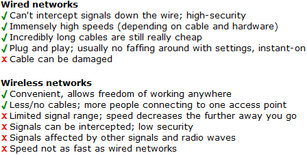
I won’t stress here much on communication technologies or protocols, what i will do is give you a short comparison between wired and wireless communication. The use of which is again purely application specific.

wired-wifi-compare

Once all of the above have been accounted for you can very well have your own local IoT setup. But you wont be able to control it or access it over the internet you always have to be in range or on the same local network on which your modified “Things” are present on.

Hence at last we come to the INTERNET part…

To be able to available on the internet the things will require the following capabilities.

Fully Capable Thing

  • With MCU(Microcontroller Unit) and Network (Each thing can directly connect to the internet)
  • The IOT application can run on the device (E.g. Smart Thermostat)

Constrained Capability

  • Only MCU (Need to connect to a network which will then connect it to the Internet)
  • No MCU (sensors send data smart hub which does processing, but can connect to the internet)
  • With networking (Each thing can communicate to each other , but will still require an external device to connect to the internet)
  • No networking (need to go through a hub which provides networking)
  • The IOT application runs as a web app on the cloud, or cloud connected dedicated server

So in conclusion you need to have knowledge of embedded systems and networking to get you kick-started with IoT.

But DIY kits like Beagle-Bone , Raspberry Pi helps speed the learning process up tremendously. For more examples of avaible DIY kits visit http://postscapes.com/internet-of-things-hardware

iot-prototype

Thanks for reading 🙂

This post was written for Inventrom by Dattaprasad Naik. Datta has been working with Inventrom since 2013 and leads Learn, the department involved in training and workshops. Follow Datta on twitter via @datta_TECH

Driver Installation Guide for all Windows Systems

Well basically this is a short post to help our students, who often face a problem of installing driver software for the programmers of Atmega based Robotics developmental boards viz UsbTINY, UsbASP and of-course TechnoBoard Lite (which doesn’t require programmers but still requires associated drivers).

Ok so to begin I will tell you’ll the routine procedure for installing drivers for any any hardware you want to attach to your system.

1) Open device manager.

2) Locate the hardware you just connected to your system either by name or it’ll sometimes show up as unknown device.

Note: For plug-n-play devices this is not the case since these devices automatically install the drivers they require for operation upon

plugin to your to system(often in the background). Also most of them have their own drivers within their memory space

(boot memory). Example USB pen drives, External hard drives, USB mouse and keyboards etc.

3) One sure way to recognize that the drivers for your external hardware are not present or not functioning properly is that the

hardware name will have a caution symbol present beside it –>caution .

4)  Select the device for which you have to manually install drivers for and right-click on it’s name.

5) Select –> Update Driver Software…

6) Windows will then open a new window with two options : a) Search automatically for updated driver software or b) Browse  computer for driver software.

7) In most cases option ‘a’ get you no where, hence it is better to have downloaded the required drivers from the internet yourself to a folder on your system

8) Hence on selecting option two you should click on Browse and direct it to the folder that contains the drivers for your hardware.

9) Upon selecting correct path and clicking on Next windows will complete the procedure of installing the driver files.

10) If the driver has been installed correctly your device should seen in the Device Manger sans the caution symbol and probably listed under one of the many categories of devices it falls under, or a completely different category for itself.


Now remember this is a general procedure but works well only if the Device Driver Signature is recognized and permitted by Windows to be installed on Windows bases OS.


So since UsbTINY and UsbASP are based on open source drivers and hardware their Device Signatures are not accepted on Windows systems 😦

A run-around for this is that Windows does allow you to remove Device Driver Signature Enforcement. Basically its like disabling a code which prevents you from installing unrecognized drivers for 3rd party hardware. 🙂


So below are the procedures for Windows versions beginning from XP right upto Windows 8.

Windows XP & Windows Vista

1) Right-click “My Computer” and click “Properties”. Following window should pop-up

xp

2) Click on Hardware tab in the above window.

xp_hw

3) Click on “Driver Signing” and it should open up a new window as shown below

xp_opt

4) In the above window click on Ignore option.

5) Click “Ok” on all windows to save settings and you should be able to install drivers by following the routine procedure detailed at the start of this post.


Windows 7 (Screen Shots Unavailable)

1) Click on “Restart” to restart your system.

2) As soon as your screen goes Black keep tapping(do not keep continuously pressed) the Function key “F8”

3) If step two is done correctly a new menu will open-up (dos type menu screen black and white)

4) On the screen select “Disable Driver Signature Enforcement” and press enter.

5) Your computer should re-start again and on start-up you should be able to install drivers by following the routine procedure detailed at the start of this post.

You can watch the video here if you are not able to follow above steps.


Windows 8

In windows 8 a lot of clicking is required so get set

Go….

Take mouse to right end of screen a pane opens up

–>Click on “Setting” (Gear icon)

Tab changes and give more option upon clicking

–>Click the bottom-most option “Change PC Settings”

A new window opens up

–>Click the “General” option on the left side.

Right Pane will change to give more options.Scroll all the way to the bottom of the right pane.

–>Click on “Restart Now” under Advanced start-up.

This should give you Three options

–>Click on “Troubleshoot” option

This should again give you Three options

–>Click on “Advanced Options”

This should give you Five options

–>Click on “Start-up Settings”

–>Click “Restart” on the next window.

This should resatrt your PC and upon restart give you an options menu with 9 options

–>Click Function key “F7” as 7th option is Disable Driver Signature.

Upon doing so your PC will restart normally and you should be able to install drivers by following the routine procedure detailed at the start of this post.

You can watch the video here if you are not able to follow above steps.


The procedure in Windows 8.1 is similar with a few changes.

In windows 8.1 too a lot of clicking is required so get set

Go….

Take mouse to right end of screen a pane opens up

–>Click on “Setting” (Gear icon)

Tab changes and give more option upon clicking

–>Click the bottom-most option “Change PC Settings”

A new window opens up

–>Click the “Update and Recovery” option on the left side.

Left Pane will change to give more options.

–> Click on “Recovery”

Right pane of window will change giving you few options.

–>Click on “Restart Now” under Advanced start-up.

This should give you Three options

–>Click on “Troubleshoot” option

This should again give you Three options

–>Click on “Advanced Options”

This should give you Five options

–>Click on “Start-up Settings”

–>Click “Restart” on the next window.

This should resatrt your PC and upon restart give you an options menu with 9 options

–>Click Function key “F7” as 7th option is Disable Driver Signature.

Upon doing so your PC will restart normally and you should be able to install drivers by following the routine procedure detailed at the start of this post.


You can watch the video here if you are not able to follow above steps.


Thanks for reading 🙂

This post was written for Inventrom by Dattaprasad Naik. Datta has been working with Inventrom since 2013 and leads Learn, the department involved in training and workshops. Follow Datta on twitter via @datta_TECH


Atmega UART tranfer data to Matlab via USB.

Before reading the blog to be able to actually understand the core working of the process one must have the some knowledge of the foll0wing:-

1) Using USART on atmega microcontrollers (code is specific to atmega 32 ).

2)Prior experience with avr studio for coding (embedded c) and knowledge to burn code onto the microcontroller.

3)Prior experience and/or knowledge of Matlab and using it on Laptop/PC.

If you feel you posses (adequately) the awesome skills mentioned above you may now continue reading the blog post 🙂

Lets start of by knowing what the USART actually is capable off.

THE USART

Ok so being specific to atmega 32 , POINTS TO REMEMBER

1)Can be used in synchronous or asynchronous mode.(We’ll be using async)

2) There are many baud rates which u can set (make sure to use the same baud rate in your Matlab code).

3) Can use parity for error correction(not used since i’m presuming communication is over short wires with not many electromagnetic interference sources nearby) 😛

4) Can select character size from 5 bits to a max of 9 bits.(we’ll stick with the standard 8-bits characters)

Point to remember sending a number from 0-255 is possible directly but numbers greater than 255 have to broken up into 8-bit data values and sent independently and then re-assembled as a whole number at the receiving end(laptop/pc). More on this later.

LETS GET CODING:

You can type(copy-paste) the code below in your version of AVRSTUDIO (i use studio5)

SAMPLE CODE:

#include <avr/io.h>

#include <avr/interrupt.h>

#include <util/delay.h>

#define F_CPU 16000000 //make sure you set this according to the freq your board operates at

#include <inttypes.h>


void uart_init(uint16_t);

char uart_read_byte(void);

void uart_write_char(char);


void uart_init(uint16_t ubrr_value) // Function to initiate UART

{

UBRRL = ubrr_value; //Baud rate setting //UBRR = (F_CPU / (16 * BAUD)) – 1 //formula

UBRRH = (ubrr_value>>8);

UCSRC=(1<<URSEL)|(3<<UCSZ0); //setting for 8-bit data tx and rx

UCSRB=(1<<RXEN)|(1<<TXEN); //Enable transmission and reception by setting RXEN and TXEN bits to 1

}


char uart_read_byte(void)             //Function to read the data

{                               // received from matlab or any other sources

while(!(UCSRA & (1<<RXC))) ;       //wait for character to  be received

return UDR; //received character present in UDR register

}


void uart_write_char(char data)      //Function to send data to

{                                    //matlab or to any other device

while(!(UCSRA & (1<<UDRE)))      //wait for transmit data buffer to go empty

UDR=data; //writing to UDR transmits the byte.

}


void main()

{

unsigned char data1;

DDRA=0x01;

uart_init(103); //9600 baud rate reffer data sheet //refer to formula in uart_init function

while(1)

{

data1=uart_read_byte();         //reading data

uart_write_char(data1);         //send same data as received

}

}// End of SAMPLE CODE

Alright once you’ve written the code, corrected for any errors, etc and have finally got a hex file with the same name as you gave for the C code, Here’s what the above code is meant to do…

It’s called an “Echo” code, simply because whatever the Microcontroller hears(Receives) it will speak out(Transmit). The comments in the code make it pretty self explanatory if you follow it step by step.


Next burn the code and your Microcontroller is ready to communicate with a PC.

No not really 😛

You will need an interface between your PC and the microcontroller for them to understand each other.  (Communication protocols differ)

Assuming you want to communicate to your laptop/PC via the USB port(Serial ports not considered). You will need a convertor, more specifically USB to TTL convertor. One such is available on the following Link (tried and tested).

usb_to_serial_ttl_cmos_logic

(http://www.nex-robotics.com/index.php?option=com_virtuemart&page=shop.product_details&flypage=flypage.tpl&category_id=59&product_id=267&Itemid=45)

You must download the drivers and the serial terminal present in the same link.

Also you will require USB cable with TYPE ‘B’ USB connector at one end and TYPE ‘A’ USB connector at the other end.

https://i0.wp.com/ecx.images-amazon.com/images/I/4109I2PdxCL._SY300_.jpg

The USB is interfacing with the convertor module is quite straightfoward.

When you are using this module for first time then install its necessary drivers by downloading and installing drivers from the same link.

DRIVER INSTALLATION GUIDE:

1) Connect USB cable to PC and convertor module.

2) Open “Device Manager” on your system.

3) Search for the device marked in image below.


4) Right-click and click on “Update Device Driver Software”

5) A new pop-up window will then ask you whether you want windows to search for the driver online or if u have it on your system. Select browse my system option.

6) Assuming you have downloaded the driver and unzipped it into some directory on your system, you should be able to select the driver folder from the directory you have unzipped the files into.

7) Once you have selected the driver folder it’s path will appear in the window. Click on “Next” and windows will do the needful 🙂

8) If everything has worked the way its meant to work your “Device Manager” will list the convertor module under PORTS(COM & LPT). (Refer to Image below. )

com port

P.S. The com port number will differ from user to user and should be noted down for further use.

This concludes interfacing convertor module to your PC.


Now we have to interface the convertor module to the Microcontroller.

Interfacing the convertor module with the microcontroller however requires some inspection of the microcontroller  datasheet , specifically the Pin Configurations. For your convenience I have added the DIP package Pin Config of ATmega 32 below.

pinout_atmega32

As shown in the pin config , the RX pin is PORTD pin0 and the TX pin is PORTD pin1.

You will also find RX and TX pins marked on the convertor module. Refer to image below.

convertor


We have to make the connections as follows

Rx of UC (PORTD Pin0)–> Tx of convertor module

Tx of UC (PORTD Pin1)–> Rx of convertor module

Also Ground of Uc –> Ground of convertor module(GND).

Lastly the jumper(marked red) present on the Convertor module should be on the 5v Logic side. Since ATmega TTL logic is at 5v.

(Brotip: If you want to interface raspberry pi the same way you must shift the jumper t0 3.3 v Logic)

This gives us the Null modem configuration.

Now we are finally ready to communicate with PC. The convertor will now act as an interface(communiction translator) between the microcontroller and your pc.

To test the configuration we will use serial terminal program also available in the same download link.

After downloading and installing the serial terminal program open the same.

serial terminal

The above window is the User interface of the serial terminal program.

First select the COM PORT number as assigned to the convertor module by your system.

Baud Rate:9600 ; Parity: None ; Data Bits:8 ; Stop Bits:One ; Data Mode: Text … These are set by default and match the communication protocols we have set for the USART of the ATmega 32 in our C program.

After the settings are done click on Connect.

Now presuming you have burnt the sample “Echo” code onto your microcontroller. Within the UI of the serial terminal program you can type any character you wish to send to the microcontroller by typing it in the “Send Data” field and click on “Send”.

serial terminal send

If you receive the same character back in the Text Area you have successfully set up communication between your PC and and the Micro controller. *round of applause* 🙂

Now for the main part i.e. Getting Data into Matlab for further processing, since that was our main aim to begin with.

To understand serial communication in Matlab first you have to understand the meaning of each Instruction that will be used in the Matlab program.


1)serial

Create serial port object

Syntax:

obj = serial(‘port’)

obj = serial(‘port’,’PropertyName’,PropertyValue,…)

Description:

obj = serial(‘port’) creates a serial port object associated with the serial port specified by port. If port does not exist, or if it is in use, you will not be able to connect the serial port object to the device.Port object name will depend upon the platform that the serial port is on. instrhwinfo (‘serial’) provides a list of available serial ports. This list is an example of serial constructors on different platforms: Platform Serial Port Constructor

Linux and Linux 64serial(‘/dev/ttyS0’);

Mac OS X 64serial(‘/dev/tty.KeySerial1’);

Windows 32 and Windows 64serial(‘com1’);


obj = serial(‘port’,’PropertyName’,PropertyValue,…) creates a serial port object with the specified property names and property values. If an invalid property name or property value is specified, an error is returned and the serial port object is not created.

Example:

s = serial(‘COM11′,’BaudRate’,9600,’DataBits’,8);          //obj “s” will refer to a com port “11” with “9600” as baud rate setting and character size of “8” data bits.

2)   fopen (serial)

Connect serial port object to device

Syntax:

fopen(obj)

Description:

fopen(obj) connects the serial port object, obj to the device.


3)   BytesAvailable

Number of bytes available in the input buffer

Description:

BytesAvailable indicates the number of bytes currently available to be read from the input buffer. The property value is continuously updated as the input buffer is filled, and is set to 0 after the fopen function is issued.

You can make use of BytesAvailable only when reading data asynchronously. This is because when reading data synchronously, control is returned to the MATLAB command line only after the input buffer is empty. Therefore, the BytesAvailable value is always 0.

The BytesAvailable value can range from zero to the size of the input buffer. Use the InputBufferSize property to specify the size of the input buffer. Use the ValuesReceived property to return the total number of values read.


4)    BytesToOutput

Number of bytes currently in the output buffer

Description:

BytesToOutput indicates the number of bytes currently in the output buffer waiting to be written to the device. The property value is continuously updated as the output buffer is filled and emptied, and is set to 0 after the fopen function is issued.

You can make use of BytesToOutput only when writing data asynchronously. This is because when writing data synchronously, control is returned to the MATLAB command line only after the output buffer is empty. Therefore, the BytesToOutput value is always 0.


5)fclose (serial)

Disconnect serial port object from device

Syntax:

fclose(obj)

Description:

fclose(obj) disconnects obj from the device, where obj is a serial port object or an array of serial port objects.


6)fprintf (serial)

Write text to device

Syntax:

fprintf(obj,’cmd’)

fprintf(obj,’format’,’cmd’)

fprintf(obj,’cmd’,’mode’)

fprintf(obj,’format’,’cmd’,’mode’)

Description:

fprintf(obj,’cmd’) writes the string cmd to the device connected to the serial port object, obj. The default format is %s\n. The write operation is synchronous and blocks the command-line until execution completes.

fprintf(obj,’format’,’cmd’) writes the string using the format specified by format.

fprintf(obj,’cmd’,’mode’) writes the string with command line access specified by mode. mode specifies if cmd is written synchronously or asynchronously.

fprintf(obj,’format’,’cmd’,’mode’) writes the string using the specified format. format is a C language conversion specification.

You need an open connection from the serial port object, obj, to the device before performing read or write operations.

Use the fopen function to open a connection to the device. When obj has an open connection to the device it has a Status property value of open. Refer to Troubleshooting Common Errors for fprintf errors.

To understand the use of fprintf refer to Completing a Write Operation with fprintf and Rules for Writing the Terminator.


7)fwrite (serial)

Write binary data to device

Syntax:

fwrite(obj,A)

fwrite(obj,A,’precision’)

fwrite(obj,A,’mode’)

fwrite(obj,A,’precision’,’mode’)

Description:

fwrite(obj,A) writes the binary data A to the device connected to the serial port object, obj.

fwrite(obj,A,’precision’) writes binary data with precision specified by precision.

precision controls the number of bits written for each value and the interpretation of those bits as integer, floating-point, or character values. If precision is not specified, uchar (an 8-bit unsigned character) is used. The supported values for precision are listed below in Tips.

fwrite(obj,A,’mode’) writes binary data with command line access specified by mode. If mode is sync, A is written synchronously and the command line is blocked. If mode is async, A is written asynchronously and the command line is not blocked. If mode is not specified, the write operation is synchronous.

fwrite(obj,A,’precision’,’mode’) writes binary data with precision specified by precision and command line access specified by mode.


8)fscanf (serial)

Read data from device, and format as text

Syntax:

A = fscanf(obj)

A = fscanf(obj,’format’)

A = fscanf(obj,’format’,size)

[A,count] = fscanf(…)

[A,count,msg] = fscanf(…)

Description:

A = fscanf(obj) reads data from the device connected to the serial port object, obj, and returns it to A. The data is converted to text using the %c format.

A = fscanf(obj,’format’) reads data and converts it according to format. format is a C language conversion specification. Conversion specifications involve the % character and the conversion characters d, i, o, u, x, X, f, e, E, g, G, c, and s. Refer to the sscanf file I/O format specifications or a C manual for more information.

A = fscanf(obj,’format’,size) reads the number of values specified by size. Valid options for size are:

n=Read at most n values into a column vector.

[m,n] =Read at most m-by-n values filling an m–by–n matrix in column order.

Size cannot be inf, and an error is returned if the specified number of values cannot be stored in the input buffer. If size is not of the form [m,n], and a character conversion is specified, then A is returned as a row vector. You specify the size, in bytes, of the input buffer with the InputBufferSize property. An ASCII value is one byte.

[A,count] = fscanf(…) returns the number of values read to count.

[A,count,msg] = fscanf(…) returns a warning message to msg if the read operation did not complete successfully.


Matlab Code

Type this code one after the another in command window

>>s = serial(‘COM11′,’BaudRate’,9600,’DataBits’,8);

>> fopen(s)

>>fwrite(s,’1’);

>>A=fscanf(s,’%c’,s.BytesAvailable);

>>disp(A); //display received character, should be same as sent character

>> fclose(s)


This post was written for Inventrom by Dattaprasad Naik. Datta has been working with Inventrom since 2013 and leads Learn, the department involved in training and workshops. Follow Datta on twitter via @datta_TECH


Yipeeee ! We have a blog.

Wohooo !!! We now have a blog.

Feels great to finally launch a blog for Inventrom. We had this on our mind for a long time but 8th December is finally the auspicious day. 🙂

We look forward to this space to share about our products and technologies you. Our awesome experience with robotics and how you can make your experience with robotics awesome.

So stay tuned, keep reading and Happy Roboting !